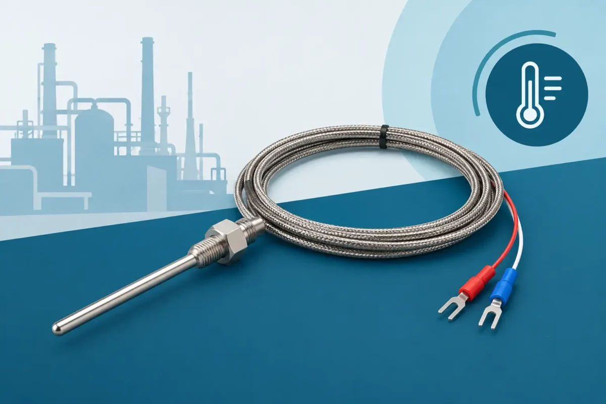
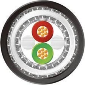
The correct thermocouple cable preserves the accuracy of temperature measurement in industrial processes, even under heat, electrical noise, and continuous mechanical stress.
A deviation of even a few degrees can compromise the quality of a reaction, increase the energy consumption of a furnace, or prematurely shut down a critical asset. Therefore, the thermocouple cable should not be treated as a simple conductor between the sensor and the instrument: it is an active part of the measurement chain. Its selection must preserve the electromotive force of the circuit, withstand the installation environment, and maintain a stable reading throughout operation.
In demanding applications, an inappropriate cable choice can introduce errors that appear to be sensor, controller, or transmitter failures. In practice, the cause may lie in an incompatible extension, reversed polarity, degraded insulation, or proximity to power circuits. Specification engineering begins with understanding the application, not just the type of thermocouple installed.
What differentiates a thermocouple cable?
A thermocouple measures temperature based on the voltage generated by the junction of two different metals. This voltage is small and varies according to the metal combination and the temperature difference between the measuring junction and the reference junction. When extending this circuit, the materials used in the cable must exhibit thermoelectric behavior compatible with the sensor. Otherwise, parasitic voltages arise and, consequently, reading errors occur.
This requirement distinguishes a thermocouple cable from a conventional instrumentation cable . A common copper pair can physically conduct the signal, but it does not maintain the required thermoelectric characteristic between the measurement point and the equipment. For industrial applications, this difference directly affects process reliability.
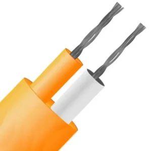
Cables can be broadly classified as extension or compensation cables. Extension cables use alloys equivalent to those of the thermocouple within a defined temperature range. Compensation cables, on the other hand, use alternative alloys, developed to reproduce the thermoelectric response of the assembly within defined application limits. The choice depends on the type of thermocouple, the temperature the cable will encounter along its path, the required precision, and the standards adopted by the project.
Thermocouple cable: compatibility starts with the type.
Types J, K, T, E, N, R, S, and B are not interchangeable. Each has its own metallic pairs, operating ranges, sensitivities, and identification codes. A cable intended for type K, for example, should not be used in a shield with a type J sensor simply because it has the same number of conductors or a similar appearance.
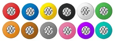
Correct identification must consider the standard defined for the project. The IEC 60584 and ANSI/ASTM references establish tolerance, designation, and identification criteria, but color codes may vary depending on the normative system used. In installations with imported equipment, this verification prevents recurring errors during assembly and maintenance.
It is also necessary to confirm the polarity throughout the entire chain. Reversing the conductors can cause the reading to drop when the temperature rises, generate inconsistent readings, or trigger false alarms. In thermocouples, the identification of the positive pole should not be assumed from practices applied to control cables. The manufacturer's documentation, insulation marking, and commissioning tests should be the reference.
Extension, compensation and tolerance
The tolerance class defines the permissible deviation of the cable from the reference thermoelectric curve. The more critical the measurement, the smaller the acceptable margin of error should be in the sensor, cable, connections, and instrument assembly. It is pointless to specify a high-precision thermocouple and install a cable whose tolerance makes the final result unachievable.
There is also an ambient temperature limit for the cable. A compensating material may function adequately in protected panels and routes, but lose its stability if continuously exposed to higher than expected heat. Therefore, process temperature is not the only relevant data: the actual temperature in the tray, conduit, classified area, or near the equipment also needs to be included in the analysis.
Insulation and coverage for the real environment.
The combination of insulation and outer covering determines how long the cable will maintain its electrical and mechanical properties. In dry and protected areas, conventional solutions may suffice. However, in furnaces, ovens, heat treatment lines, foundries, and near heated surfaces, high-temperature materials become indispensable.
Fiberglass, silicone, fluoropolymers, and other special compositions can be used depending on the thermal, chemical, and mechanical conditions. Each alternative involves trade-offs. Insulation with excellent high-temperature performance may have lower abrasion resistance; another may withstand specific chemical agents but require greater care during installation. The selection should consider the complete operating cycle, including start-up, cleaning, maintenance, and unscheduled shutdowns.
In environments with oil, fuels, humidity, salt spray, or chemicals, chemical compatibility requires specific validation. The same applies to outdoor areas, where ultraviolet radiation, temperature variations, and water ingress accelerate the aging of the sheathing. For naval, oil and gas, mining, or chemical processing applications, meeting the nominal temperature is not enough: the cable must withstand the combined agents present in the field.
Electrical noise, shielding, and installation route
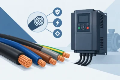
A thermocouple signal is weak and vulnerable to electromagnetic interference. Frequency inverters, motors, direct starters, transformers, welding, and nearby power cables can induce noise in the measurement. The effect appears as temperature fluctuation, instability in the control, or alarms that do not correspond to the actual process condition.
Electrostatic shielding helps reduce this risk, but it only works when specified and grounded according to the automation architecture. In general, grounding the shielding at a single point prevents circulating currents, although there are designs with particular requirements. This definition must be aligned with the plant's grounding standard and the control system manufacturer.
The physical route also makes a difference. Whenever possible, thermocouple cables should be segregated from power circuits, especially motor feeders and inverter output cables. When crossing is unavoidable, routing at an angle close to 90 degrees reduces coupling. Metallic conduits, dedicated trays, and adequate distances complement the electromagnetic immunity strategy.
Splices and connections require the same care.
A splice made with an unsuitable terminal can create a new thermoelectric junction and alter the reading. For this reason, connectors, terminals, and heads need to be compatible with the thermocouple type and the temperature of the installation point. The indiscriminate use of copper connectors is a classic source of deviation, especially when there is a thermal gradient in the junction box.
Splices should be minimized and documented. When necessary, it is recommended to install them in accessible, protected boxes with clear identification of the type, polarity, and circuit. This precaution reduces diagnostic time in future interventions and prevents incorrect replacements during corrective maintenance.
How to specify to avoid field failures
A complete specification begins with the type of thermocouple and the accuracy required by the loop. It then assesses the circuit length, ambient temperature along the path, chemical exposure, shielding requirements, flexibility, installation method, and applicable project standards.
It is also essential to define the mechanical construction. Cables installed in mobile machines , furnace doors, transfer cars, or equipment subject to vibration require greater flexibility and fatigue resistance. In fixed routes, the priority may be different, such as fire behavior, low smoke emission, oil resistance, or impact protection.
The technical documentation should specify at least the thermocouple type, tolerance class, temperature range, conductor configuration, insulation and sheathing materials, shielding, outside diameter, and reference standard. This level of detail reduces divergent interpretations between design, purchasing, installation, and maintenance.
When a project encounters unconventional conditions, on-demand manufacturing is a technical advantage. Innovcable develops special cables considering application requirements, mechanical performance, operating environment, and regulatory compliance. "Your Project, Our Engineering" means transforming process data into a solution that makes sense in the field, not just on a bill of materials.
Signs that the circuit needs to be checked.
Unstable readings, persistent differences between nearby sensors, inverted indications, and deviations after maintenance are reasons to investigate the entire circuit. Before replacing the thermocouple, it is worth checking continuity, polarity, intermediate connections, insulation condition, shielding, and proximity to sources of interference.
Visual inspection also provides relevant evidence. Dryness, hardening, cracks, crushing, heat discoloration, and water infiltration in enclosures are signs that the cable may have exceeded its design specifications. In a critical operation, waiting for total failure is rarely the most economical decision.
Temperature measurement is only as reliable as the weakest link in the loop. By specifying the thermocouple cable with the same rigor applied to the sensor and the instrument, the industry protects process quality, reduces unproductive diagnoses, and maintains operational decisions based on data that truly represent the field.