Learn how to test cable continuity with a multimeter, avoid false readings, and determine when testing requires specialized engineering inspection.
An intermittent shutdown in a panel, a communication failure in the field, or a valve failing to activate can all originate from a broken conductor. Knowing how to test cable continuity allows you to quickly locate this condition, but the result is only reliable when the circuit is de-energized, isolated, and correctly identified. In industrial applications, a simple beep from a multimeter does not replace an analysis of the electrical and mechanical integrity of the assembly.
The continuity test is a basic, yet crucial, check in the maintenance, commissioning, and inspection of cables. It confirms whether a low-resistance electrical path exists between two points on the same conductor. It does not, by itself, confirm insulation capacity, voltage withstand capability, contact resistance under load, or the suitability of the cable for the operating environment.
What does the continuity test actually verify?
When a multimeter applies a small current between its probes, it measures the resistance of the electrical path. If this resistance is below the limit set by the instrument, the equipment emits a beep or displays a value close to zero ohms. In practice, this indicates that the conductor is not open between the points tested.
The test is particularly useful for identifying breaks in control, instrumentation, command, low-voltage power supply, and multi-core cables. It also helps to verify the correspondence between terminals during panel assembly or to trace a conductor in circuits without proper identification.
There is an important caveat: continuity does not mean total quality. A cable may exhibit continuity and still have degraded insulation due to moisture, abrasion, heat, chemical agents, or mechanical stress. In cables subjected to continuous bending, movement on conveyors, robotic twisting, or vibration, there may be partial failure that manifests itself only during movement or under load.
How to test cable continuity step by step.
Before positioning the test probes, treat the circuit as energized until the absence of voltage is verified. In industrial installations, follow the applicable lockout/tagout procedure, in addition to plant safety requirements and current regulations.
1. De-energize, lock out, and confirm the absence of voltage.
Disconnect the power supply from the circuit, perform the restart lockout, and confirm the absence of voltage with the instrument set to the correct range. Do not use the continuity function to check for voltage presence. This practice can damage the multimeter and expose the professional to electrical hazards.
Disconnect cables from equipment whenever possible. Inverters, PLCs, power supplies, relays, sensors, and electronic modules can create parallel paths that alter readings. Additionally, some devices can be damaged by improper testing procedures.
2. Inspect the cable before measuring.
Visual inspection guides the diagnosis. Look for crushing, cuts, excessive bending, cracks in the covering, localized heating, water ingress, oxidation on terminals, and points of friction. In mobile installations, also assess cable glands, bending radii, fasteners, and areas of higher mechanical stress.
If visible damage is present, the continuity test should not be used as a criterion for releasing the cable for service. The integrity of the sheathing and insulation must be assessed according to the voltage, circuit criticality, and installation maintenance procedure.
3. Configure and validate the multimeter.
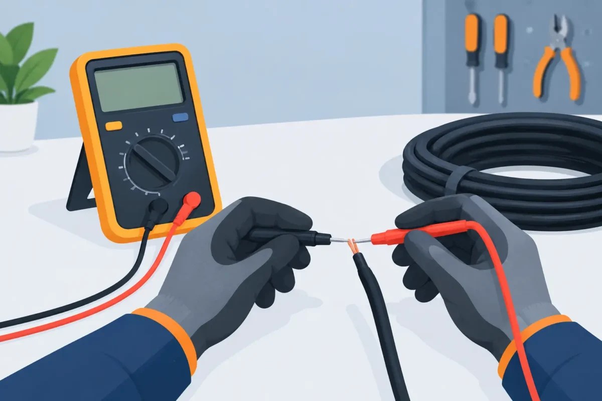
Select the continuity function, usually identified by the sound wave symbol, or the resistance scale in ohms. Touch one probe to the other. The instrument should indicate a very low resistance value and, in the appropriate function, emit an audible warning.
This simple check confirms that the probes, measuring leads, and multimeter are responding. In low-resistance measurements, the resistance of the probes themselves can influence the displayed value. For a continuity check, this is usually acceptable. For technical evaluation of conductor resistance, the method, compensation, and accuracy of the instrument must be more rigorously defined.
4. Measure from one end to the other.
Connect one probe to a terminal on the conductor at one end and the other probe to the corresponding terminal at the other end. If there is continuity, the multimeter will indicate low resistance or emit a beep.
In a long cable, the resistance will naturally be higher than in a short section. The conductor's nominal cross-section, material, length, and temperature all influence this result. Therefore, interpret the value by comparing it to the installed length and the cable's construction characteristics, not just by whether or not the instrument beeps.
When the ends are far apart and two people are not available, make a temporary bridge at one end of the cable between the conductor under test and an identified return conductor. At the other end, measure between the two conductors. When finished, remove the bridge and record the correct identification to avoid connection errors.
5. Test each route and confirm identification.
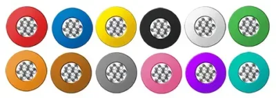
In multi-core cables, test each conductor individually. The color, numbering, sequential marking, and electrical diagram should guide the verification. Do not assume that two conductors with similar colors correspond to the same circuit, especially in repairs, extensions, or old installations.
The test sequence must be documented in critical systems. Recording the cable, the section, the terminals evaluated, the result, and the date facilitates traceability and prevents a recurring failure from being treated as an isolated occurrence.
How to avoid false readings in continuity testing.
A positive reading can occur through parallel electrical paths. Relay coils, lamps, resistors, control circuits, shared grounds, and electronic components can allow sufficient current to pass through to trigger the audible signal. For this reason, the cable must be isolated from other circuit elements during testing.
The opposite can also occur. Poor contact at the terminal, a poorly supported probe, oxidation, or an intermittent fault can indicate an open circuit, even though the conductor is intact. Repeat the measurement at clean metal points and apply a slight, controlled movement to the cable when it is safe to do so. If the reading fluctuates, investigate the section subjected to bending, the connectors, and the terminations.
In shielded cables , maintain the distinction between shielding, drain, and live conductors. Shield continuity may be necessary for the system's electromagnetic compatibility strategy, but it should not be confused with signal path continuity. Shield connection at one or both ends depends on the electrical design and interference environment.
Continuity, isolation and resistance: different tests
A multimeter is suitable for locating leaks and checking connections, but it has clear limitations. To check for leakage between conductors or between a conductor and ground, it is necessary to assess the insulation resistance with an instrument and test voltage appropriate to the cable and circuit. This procedure requires extra care, as it applies a higher voltage than a standard multimeter and can damage connected electronics.
The electrical resistance of the conductor is relevant in power circuits, long distances, motor starting, and applications where voltage drop and heating are design factors. The presence of continuity does not guarantee that the resistance is within the expected range. A partially broken conductor or a faulty termination may conduct the test current but fail under load.
In fire safety systems, process instrumentation, critical automation, energy, mining, marine environments, and areas with high downtime costs, the definition of tests must consider design, applicable standards, rated voltage, service class, and operational criticality. Testing without a defined acceptance criterion transforms field data into a weak conclusion.
When to replace the cable instead of just repairing it.
If the fault is limited to a poorly executed termination, a qualified intervention may restore the circuit. However, cables with compromised sheathing, signs of bending fatigue, crushing deformation, chemical exposure, or overheating should be evaluated in addition to continuity. Spot repair may restore electrical contact, but not necessarily the service life required for reliable operation.
Correct specification reduces the recurrence of these failures. Cables for conveyors, robotics, lifting, naval areas , photovoltaic systems, or instrumentation circuits face distinct demands regarding bending, abrasion, temperature, oil, humidity, electromagnetic interference, and voltage. The selection should be based on the actual operating conditions , not just the conductor cross-section or the lowest initial cost.
Innovcable develops solutions for industrial applications where electrical performance, mechanical strength, and technical compliance must work together. When failure history indicates incompatibility between cable and application, specification engineering is as relevant as field diagnostics.
The continuity test should be viewed as an objective decision-making step: it shows whether an electrical path is available, but the safe release of the circuit depends on understanding why the fault occurred, what stresses the cable is under, and what performance conditions the operation requires.