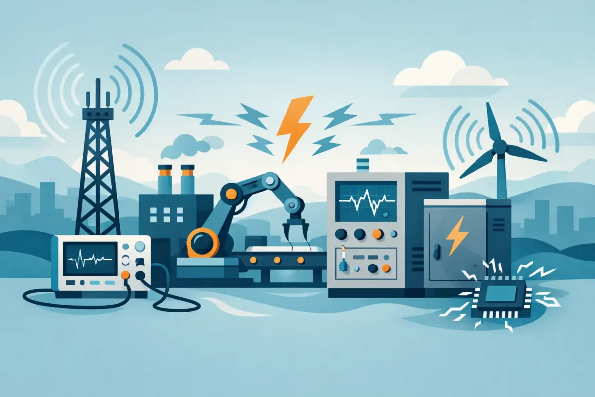
This guide on industrial electromagnetic compatibility provides guidance on specifying cables and grounding to reduce faults, noise, and plant downtime.
A frequency inverter can operate without alarms during commissioning and, days later, cause unstable instrument readings, communication failures, or unintended tripping in a plant. This guide on industrial electromagnetic compatibility addresses precisely this risk: how to design, install, and validate electrical systems capable of coexisting with electromagnetic noise without compromising control, safety, and operational availability.
Electromagnetic compatibility, or EMC, is not just a compliance requirement. In industrial environments, it determines whether low-power signals will remain intact alongside high-energy drives, motors, contactors, switched-mode power supplies, radios, and circuits. When EMC is neglected, the consequence can be a difficult-to-diagnose shutdown, loss of process data, or incorrect activation of protection devices.
What is industrial electromagnetic compatibility?
Electromagnetic compatibility is the ability of a device or system to function properly in its electromagnetic environment without generating intolerable disturbances to other equipment. In industry, this definition involves two simultaneous requirements: controlling the emissions produced by a device and ensuring sufficient immunity against external interference.
An inverter, for example, generates fast switching pulses and high-frequency harmonics. These phenomena can propagate by conduction in power cables and by radiation to nearby cables. If an instrumentation, encoder, or communication circuit is exposed without adequate protection, the useful signal may be altered.
The problem is rarely in a single component. Interference results from the combination of the emitting source, the coupling path, and sensitive equipment. Therefore, simply replacing the cable or adding a filter without analyzing the architecture may alleviate a symptom, but not eliminate the cause.
Emissions, immunity, and coupling pathways
Conducted emissions travel through power lines, ground, and shielding. Radiated emissions, on the other hand, propagate through space, especially when long cables act as antennas. The system's susceptibility depends on the noise frequency, the voltage or current level involved, the circuit impedance, and the quality of the terminations.
In practice, four mechanisms deserve attention: capacitive coupling between nearby conductors, inductive coupling through magnetic fields, common impedance coupling at grounding, and radiated coupling. Each requires a different engineering response. The distance between routes can solve part of an inductive problem, but it does not compensate for poorly terminated shielding in a high-frequency cable.
Guide to industrial electromagnetic compatibility in cable specification.
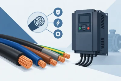
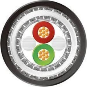
The cable plays an active role in EMC performance. Its construction, geometry, shielding, metallic sheathing, twisted pairs, capacitance, and installation method define how efficiently the system limits noise. The selection should be based on the application, not just on nominal voltage, conductor cross-section, or stock availability.
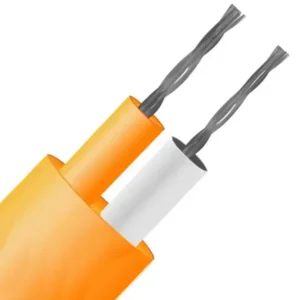
In instrumentation cables, twisted pairs reduce the pickup of common-mode and differential-mode interference. When there are low-intensity analog signals, such as 4-20 mA, thermocouples, or transducers, the shielding must be dimensioned according to the electromagnetic environment and the grounding strategy. For industrial networks, the characteristic impedance, pair symmetry, and shielding continuity directly affect protocol integrity.
Cables for servomotors and frequency inverters require even greater attention. PWM switching imposes high dv/dt values, common-mode currents, and additional stress on insulation, shielding, and grounding systems. In this application, a suitable cable must combine a construction compatible with movement or fixed installation, low-impedance shielding at high frequencies, and materials suitable for the thermal, chemical, and mechanical environment.
Shielding should not be viewed as a generic layer . A copper braid offers different behavior than a metallic tape, and a combination of both may be necessary depending on the frequency range and the required level of coverage. Electrical continuity along the path is also important, including splices, cable glands, connectors, metal boxes, and panels.
Grounding and equipotential bonding: where many projects fail.
Shielding only delivers the expected performance when it has a correct grounding reference. At high frequencies, long grounding conductors present significant impedance. For this reason, a short, wide connection with a large contact area is usually more efficient than a thin, long conductor connected to a distant point.
It is necessary to differentiate between protective grounding, functional reference, and equipotential bonding. Although they may be connected in the same architecture, their functions are not identical. Protective grounding ensures safety against electric shocks; functional grounding provides a reference for specific circuits; and equipotential bonding reduces potential differences between structures, panels, machines, and metallic pathways.
In systems with inverters, 360-degree termination of the shielding on metal connectors and cable glands is often more effective than using a long pigtail. The pigtail increases inductance and reduces shielding efficiency at high frequencies. Even so, the decision regarding grounding at one or both ends depends on the application, the frequency involved, the type of signal, and the possibility of ground loops. There is no single rule valid for all circuits.
Routing: distance, segregation, and intersections
The coexistence of power and signal cables requires physical organization. Long parallel routes increase coupling, especially when motor or feeder cables pass alongside control circuits. Whenever possible, the routes should be segregated into separate cable trays, conduits, or raceways, with separations defined by energy level, shielding type, and signal sensitivity.
When crossing routes is unavoidable, it should occur at approximately 90 degrees. This reduces the coupling length between conductors. It is also recommended to avoid encoder, communication, and instrumentation cables sharing panel inputs with inverter output cables without metallic barriers or adequate separation.
The infrastructure material influences the outcome. Properly interconnected metal cable trays can contribute to shielding and equipotential bonding. However, discontinuities, insulating paints, splices without electrical contact, and poorly grounded sections reduce this contribution. The installation should be evaluated as a whole, not as a sequence of independent items.
How to diagnose EMC faults in the field.
Electromagnetic faults tend to be intermittent. They may only appear during motor acceleration, the switching of an inductive load, the simultaneous operation of several inverters, or a specific humidity and temperature condition. Therefore, diagnosis should begin by correlating the event with the plant's operational status.
Record times, alarms, activated loads, motor speeds, recipe changes, and signal behavior. Then, check cable routing, shielding continuity, grounding points, and proximity to noise sources. Measurements with an oscilloscope, spectrum analyzer, high-frequency current clamp, and appropriate instruments help identify noise components that a conventional multimeter does not reveal.
Avoid trial-and-error fixes without documentation. Installing ferrites, filters, or additional conductors may alter the system's behavior, but the measure needs to be validated under real load conditions. The effective solution is one that reduces disturbance without creating undesirable effects such as overheating, voltage drop, loss of communication, or difficulty in maintenance.
Standards and project validation
EMC compliance must consider the standards applicable to the equipment, the sector, and the target market. Families such as IEC 61000 address emissions, immunity, and test methods, while product standards may establish specific limits and conditions. In projects for marine , oil and gas, mining, energy, or critical infrastructure environments, additional customer and certification body requirements may define materials, tests, and documentation.
Validation should not be limited to isolated equipment. A panel approved in the laboratory may exhibit different behavior after being installed with longer cables, altered routes, inadequate grounding, or different loads. Therefore, engineering must verify the final system, including interfaces, accessories, and actual operating conditions.
At Innovcable, the development of special cables stems from this systems-oriented vision. The choice of shielding, pairs, outer sheath, and electrical characteristics must align with EMC requirements, installation, and process severity. If the risk of interference only appears in the field, the cost of correction is higher, and operational availability has already been compromised.
Designing EMC (Engine Control Modules) is about preserving reliability before noise turns into failure. A well-executed specification creates operational headroom, simplifies commissioning, and keeps signals, commands, and drives working with the predictability that critical processes demand.