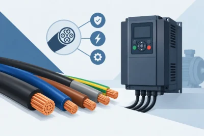
Guide to emergency circuits: choose cables, sources, routes and tests to keep critical loads operating during a fire in critical plants.
When a fire starts, electrical continuity isn't about preserving production. It's about preserving lives, guiding evacuation, and keeping the systems that control the event active. This guide to emergency circuits presents the criteria that transform this need into a specified, documented, and field-verifiable installation.
In an industrial plant, treating all circuits as if they had the same criticality is a design flaw. Common lighting, general-purpose outlets, and process loads can be switched off according to the safety strategy. However, emergency lighting, fire detection and alarm systems, booster pumps, stair pressurization, smoke exhaust systems, route signage, and communication systems must remain available for the time defined in the project.
What characterizes an emergency circuit?
An emergency circuit is one designed to power equipment essential for responding to an abnormal condition, especially during a fire or loss of the main power source. Its reliability depends on the following: alternative power source, selectivity of protections, panels, installation routes, fixing method, cables, connections, and inspection plan.
The power source can consist of a generator set, battery bank, uninterruptible power supply (UPS), autonomous power plant, or a combination of these solutions. The choice depends on the power of the loads, the required autonomy, the starting time, the operating strategy, and the requirements of the project approved by the Fire Department. A generator adequately handles large loads and long autonomy periods, but requires starting, transfer, and maintenance. Centralized battery systems can respond instantly, but have power limits and require rigorous monitoring of the condition of the batteries.
The crucial point is to define, load by load, what must remain energized and for how long. Without this criticality matrix, it is common to oversize expensive systems or, worse, fail to consider an essential load.
Guide to emergency circuits: start with the architecture.
The cable specification only makes sense after the electrical architecture has been defined. The design should physically and electrically separate safety circuits from conventional circuits whenever applicable. This segregation reduces the likelihood that the same event, such as a short circuit, mechanical impact, or thermal exposure, will simultaneously interrupt both the normal and emergency power supply.
The transfer between normal and alternative power sources also deserves attention. For loads such as escape route lighting, a few milliseconds may be acceptable when there is an adequate centralized power source. For other systems, the interruption and restart sequence should be evaluated according to the equipment's function. Pumps, fans, automation panels, and inverters may require specific logic to avoid simultaneous starts and generator overload.
The coordination and selectivity of protections are equally crucial. A fault in a terminal circuit cannot trip the feeder that supplies multiple safety systems. Circuit breaker curves, breaking capacity, short-circuit levels, relay settings, and discrimination between devices must be studied as part of the solution, not corrected only during the commissioning phase.
Classify the loads and define the autonomy.
The classification must consider the risk of the installation, the occupancy, the evacuation route, the industrial process, and the emergency plan. In a bulk terminal, for example, escape lighting and communication may have immediate priority. In an oil and gas unit, the continuity of smoke detection, suppression, and control systems may involve a more extensive architecture and more stringent installation requirements.
Autonomy should not be established for convenience. It results from applicable regulations, evacuation time, response strategy, brigade availability, and licensing requirements. ABNT NBR 10898 guides emergency lighting systems, while ABNT NBR 17240 deals with fire detection and alarm systems . ABNT NBR 5410 establishes relevant principles for low-voltage electrical installations. In addition to these references, state technical instructions, sectoral standards, and contractual requirements may prevail for each project.
Fire-resistant cables are not just flame-retardant cables.
One of the most frequent errors in specifications is confusing flame retardancy with circuit maintenance under fire conditions. A cable with flame retardant characteristics may limit the spread of fire, but it will not necessarily continue to conduct energy when subjected to high temperatures for a certain period.
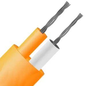
For circuits that need to operate during a fire, the central requirement is circuit integrity. Tests such as those in the IEC 60331 series verify the cable's ability to maintain electrical continuity under fire exposure, according to defined conditions and times. IEC 60332 is associated with flame propagation behavior. In occupied areas, escape routes, or installations with a high concentration of cables, criteria such as low smoke emission, halogenated gases , and acidity, evaluated in standards like IEC 61034 and IEC 60754, may also be relevant.
There is no single cable suitable for all emergency applications. The choice depends on voltage, current, permissible voltage drop, installation method, presence of oils or chemical agents, movement, humidity, and mechanical exposure. Control and instrumentation cables serving alarm systems, for example, may require shielding and identified pairs, in addition to fire performance. Pump or fan feeders demand conductors and insulation compatible with the power and thermal conditions of the load.
The installation may compromise the cable's performance.
The declared performance of the cable does not eliminate responsibility for the installation. Cable trays, conduits, supports, junction boxes, cable glands, splices, and fasteners must withstand the fire scenario predicted for that circuit. It is of little use to specify a cable with circuit integrity if the metal supports give way, if there are splices without a compatible solution, or if the route crosses a higher-risk area without adequate protection.
Avoid sharing infrastructure with common power cables when a combined failure could affect the emergency system. When sharing is unavoidable, barriers, separators, distances, compartmentalization, and the fire resistance of the installed assembly should be evaluated. The shortest route is not always the safest route.
In harsh industrial environments, analysis must incorporate vibration, salt spray, hydrocarbons, abrasion, solar radiation, humidity, and thermal cycling. A cable that is fire-resistant but incompatible with the operating environment may fail before it even fulfills its emergency function.
Electrical sizing and field validation
The sizing must consider the current carrying capacity under actual installation conditions, grouping factors, ambient temperature, voltage drop, short circuit, and protection operation. In generator-powered circuits, it is also worth analyzing transient behavior: motor starts, locked rotor current, harmonics, and impact on sensitive electronic loads.
The documentation must reflect the installation performed. Single-line diagrams, cable lists, calculation reports, certificates, technical data sheets, panel identification, and test records facilitate maintenance and traceability. In a future expansion or maintenance shutdown, this collection reduces unsafe interventions and decisions based on assumptions.
Before delivery, testing must go beyond point-in-time power-up. Verify the start-up of the alternative power source, transfer time, autonomy, command operation, operation under load, and fault signaling. In systems with detection and alarm, each point, loop, interface, and associated activation must be validated according to the approved cause-and-effect logic.
Maintenance should include visual inspection of routes, tightening of connections according to procedure, battery evaluation, generator testing, thermography when applicable, and review after process changes. A new tray, an additional panel, or a civil renovation can reduce the originally planned separation between circuits and create a vulnerability that does not appear in the diagram.
For projects with special requirements, custom manufacturing allows for aligning cable construction, materials, identification, and performance with the real-world application scenario. Innovcable operates at this stage with applied engineering for critical applications, supporting the technical definition of solutions compatible with electrical performance, installation environment, and regulatory requirements.
Emergency circuits should not be evaluated solely based on what happens when everything is functioning. The correct question is: when the installation is under smoke, heat, mains loss, and operating pressure, what loads will remain available, for how long, and through which electrical path? Designing this answer in advance is what separates a documented requirement from an effective layer of safety.