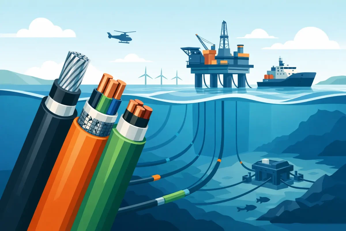
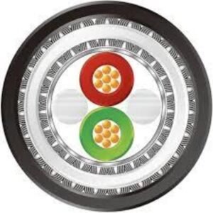
Technical guide for offshore cables with criteria for specifying materials, shielding, and standards in critical maritime operations with operational safety.
A cable failure on an offshore unit rarely boils down to replacing a single component. It can disrupt instrumentation signals, compromise communication between systems, trigger unscheduled shutdowns, and increase crew exposure to critical area interventions. This offshore cable technical guide presents the criteria that should guide cable specification to ensure the cable meets the real operating conditions, not just a generic catalog description.
In marine installations, the electrical conductor is only one part of the solution. Reliability depends on the combination of electrical construction, polymeric materials, mechanical protection, fire resistance, regulatory compliance, and installation method. Each choice must consider where the cable will be applied, which circuit it serves, and what external agents will act upon it during its service life.
What makes an offshore application different?
A platform, support vessel, FPSO, or drilling unit brings together factors that accelerate material degradation: salt spray, high humidity, hydrocarbons, continuous vibration, structural movement, solar radiation, and temperature variations. In classified areas, the integrity of the installation is also directly related to process safety.
The marine environment promotes corrosion in metallic components and can attack inadequate insulation and sheathing compounds. At the same time, cable routes coexist with crowded trays, passages through bulkheads, rotating equipment, and areas subject to washing or splashing. A cable specified only by nominal voltage and cross-section does not address this complexity.
Correct selection begins with the circuit's function. Power, control, instrumentation, telecommunications, and data cables have distinct construction requirements. An instrumentation cable, for example, must preserve low-intensity signals amidst electromagnetic interference. A power cable for a motor, on the other hand, needs to withstand the current regime, voltage drop, installation stresses, and expected thermal conditions.
Technical guide for offshore cables: specification criteria
The specification must translate operational risk into verifiable construction characteristics. This includes materials, geometry, shielding, armor, fire behavior, and technical documentation. There is no single ideal construction for every offshore installation. The solution depends on the circuit, the route, the degree of exposure, and the applicable contractual standards.
Conductor, insulation and electrical capacitance
The conductor is normally sized based on the design current , ambient temperature, installation method, grouping, and voltage drop limit . However, in offshore applications, the analysis needs to go beyond ampacity under ideal conditions. Cables grouped in trays, near heat sources, or installed in poorly ventilated compartments require consistent correction factors.
The stranding class influences flexibility and ease of assembly. In routes with vibration or where accommodation in confined spaces is required, more flexible conductors may be suitable. This does not eliminate the need to check the minimum bending radius, as an installation below the limit can damage the insulation, deform pairs, and reduce the lifespan of the assembly.
The insulation must be compatible with the voltage, operating temperature, and the possible presence of oil, fuel, or process fluids. Thermosetting and elastomeric compounds may offer advantages in applications with higher thermal and mechanical demands, but the choice must be confirmed by the service conditions. The best material for an internal fixed route will not necessarily be the most suitable for an area exposed to the deck.
External coating and resistance to the marine environment.
The coating is the first barrier against abrasion, moisture, salt spray, UV rays, and chemical agents. In exposed applications, resistance to weathering and solar radiation ceases to be a complementary attribute. In indoor areas, there may be greater priority for low smoke emission, absence of halogens, or oil resistance.
It is necessary to assess the actual contact with contaminants. There is a difference between a route subject to occasional splashes and one installed next to equipment with recurring hydrocarbon leaks. There is also a difference between cable protected in a closed cable tray and cable exposed to washing, impact, or friction against structures. An inadequate sheath can harden, crack, or lose its properties before the design deadline.
Shielding and signal integrity
Instrumentation, automation, and communication systems are sensitive to electromagnetic interference. Frequency inverters, motors, power panels, radio systems, and inductive load switching can introduce noise into measurement circuits. The result can be unstable readings, control errors, intermittent faults, and slower field diagnostics.
For instrumentation pairs, individual shielding reduces signal coupling. Collective shielding complements protection against external interference. The decision between metal foil, copper braid, or a combination of both depends on the frequency of the interference, the required flexibility, the necessary coverage, and the available grounding system.
Shielding without electrical continuity and defined grounding does not deliver the expected performance. Therefore, engineering must establish the termination strategy from the design stage, considering equipotential bonding, ground loops, and system requirements. The cable needs to be specified as part of the electrical architecture, not as an isolated item on the bill of materials.
Armor and mechanical protection
The reinforcement adds resistance to impacts, compression, tension, and potential accidental damage. It can be crucial on outdoor routes, in areas with higher mechanical risk, sections subject to falling objects, or installations without additional protection. Conversely, it increases weight, diameter, rigidity, and load-bearing requirements.
The choice of armor material deserves attention in saline atmospheres. Metallic constructions need to be evaluated for corrosion protection and compatibility with short-circuit and grounding requirements. Unarmored cables may be technically adequate when installed in conduits, protected trays, or controlled environments. The point is not to use armor as a substitute for a well-designed routing.
Fire, smoke, and operational continuity
In offshore environments, cable behavior under fire is a safety and availability requirement. Specifications may call for low smoke emission, absence of halogens, non-flame propagation, or fire resistance for a specified period. These terms are not equivalent and must be linked to the circuit's function.
Cables for emergency systems, detection and alarm systems, escape route lighting, essential pumps, or critical communication may require circuit maintenance during fire exposure. Cables installed in large bundles should be evaluated for vertical flame propagation, as the grouping significantly alters the system's behavior.
The selection must be aligned with the project standards and applicable requirements, which may include IEC and NEK-606 references , naval requirements, classification society standards, and the operator's internal standards. Compliance must be demonstrated through documentation, testing, and traceability, not just a similar commercial designation.
Installation: where many projects lose performance.
Even a properly manufactured cable can fail due to improper installation. The team must respect the minimum bending radius, maximum tensile strength, unwinding orientation, and temperature limits for handling. Larger diameter cables or those with armor require planned deployment, compatible rollers, and appropriately sized pulling points.
In terminations, moisture sealing and proper preparation of shielding, drains, and armor are crucial. Panel entries, junction boxes, and cable glands must maintain the required level of protection for the area. In classified zones, termination components must be compatible with the protection philosophy adopted in the project.
It is also recommended to maintain physical segregation between power, control, instrumentation, and communication circuits. The distance between routes, metallic barriers, and the occupancy of cable trays reduce the risks of overheating and interference. When segregation is not feasible, cable construction and shielding strategy become even more important.
How to transform an operational requirement into a manufacturable cable
A good specification should not be limited to phrases like "offshore cable" or "marine cable". To develop a suitable solution, the manufacturer needs to receive objective data: voltage and current, signal type, number of conductors or pairs, cross-section, temperature, installation route, chemical exposure, shielding requirements, armor requirements, fire behavior, and mandatory standards.
Special projects often require a balance between competing requirements. A more heavily armored construction can increase weight and make installation more difficult. A sheath with high chemical resistance may not be the best option for continuous bending. More complete shielding can increase diameter and cost. The right decision is the one that controls the predominant risk without creating a new problem in assembly or maintenance.
On-demand manufacturing allows these elements to be tailored to the project context, with material validation, dimensional controls, electrical testing, and batch traceability. Innovcable acts as an engineering partner in this area, transforming application requirements into special cables that meet technical standards and are compatible with field realities.
Before authorizing a purchase, it's worth reviewing whether the proposed cable has been analyzed for the route where it will actually be installed, for the circuit it will actually serve, and for the fault conditions that the operation cannot accept. In offshore operations, this specification discipline is what keeps power, signals, and safety operational when access to correct an error is more expensive and complex.