Installing photovoltaic cables requires proper selection, protected routing, compatible connections, and inspection to maintain safety and continuous generation.
An insulation fault, an incompatible connector, or an undersized cable can compromise the availability of a power plant for much longer than the installation itself. The installation of photovoltaic cables is not an accessory step in the project: it determines electrical safety, generation stability, and maintenance costs throughout the system's lifespan.
In residential, commercial, or large-scale applications, the cable needs to withstand the electrical conditions of the circuit and, most importantly, the environment in which it will remain exposed for decades. Solar radiation, humidity, heat, thermal variations, mechanical stress, and chemical agents are all part of the field reality. Therefore, a correct specification only delivers results when accompanied by consistent assembly, protection, and commissioning practices.
What defines a reliable photovoltaic cable installation?
A photovoltaic system combines direct current circuits between modules, strings, junction boxes, and inverters, as well as alternating current circuits after energy conversion. Although both sides are part of the same system, they have different voltage, current, protection, and routing characteristics. Treating the entire installation as a single cable infrastructure is a mistake that hinders inspections and increases the risk of failures.
On the DC side, voltage may remain present during the irradiance period, even when the inverter is switched off. This requires special attention to insulation, connector integrity, and reducing the risk of electric arcs. On the AC side, coordination between cables, circuit breakers, surge protection devices, and grounding becomes central to operational continuity.
The quality of the installation depends on the combination of five technical decisions: electrical sizing, cable type, installation method, connection compatibility, and final validation. If any of these are neglected, the expected durability of the system becomes unreliable.
Sizing begins with the actual operating conditions.
The nominal conductor cross-section should not be defined solely by the total power of the power plant. The calculation must consider the design current of each circuit, the maximum system voltage, the current carrying capacity, the permissible voltage drop, the ambient temperature, the estimated cable temperature, the grouping, and the installation method.
In the field, cables installed in exposed cable trays, enclosed conduits, raceways, or buried dissipate heat differently. There is also a difference between an isolated section and several circuits run in parallel along the same path. When there is grouping, the temperature rise reduces the current carrying capacity and may require a larger cross-section.
Voltage drop deserves evaluation from the strings to the AC connection point. An excessively limited design may operate without immediate tripping, but it creates continuous generation losses. In power plants with long distances between arrays, inverters, and metering centers, this analysis directly influences the return on investment.
It is also necessary to verify short-circuit withstand capability and compatibility with the protection devices foreseen in the project. The choice must be documented in a calculation report, not based solely on repeated practices from previous installations.
Cables for the DC side: environmental resistance is a requirement.
The photovoltaic cable used between modules and inverters must be suitable for direct current and for prolonged exposure to the elements, when this is the condition of use. Its construction must meet the system's voltage levels and offer resistance to UV radiation, ozone, humidity, heat, and weathering.
The flexibility of the conductor also matters. In runs over fixed structures, with changes of direction and anchor points, a flexible cable facilitates assembly without compromising the minimum bending radius. Sharp bends or pinching against metal corners can damage the insulation, even if the defect is not visible at the time of delivery.
Applicable standards, such as ABNT NBR 16612 for power cables intended for photovoltaic systems, should guide the specification in accordance with project requirements, utility company requirements, and relevant electrical installation standards. For special applications, the requirement may include additional characteristics such as low smoke emission , chemical resistance, or performance in harsh industrial environments.
Cables for the AC side: integration with the electrical installation.
After the inverter, the cables must be specified according to the alternating current regime, the installation method, and the circuit conditions. It is common for the design focus to be concentrated on the strings, while the sections between inverters, switchboards, transformers, and connection points receive a simplified analysis. This decision can lead to overheating, losses, and difficulties in future expansion.
In commercial and industrial installations, AC cable routing must consider electromagnetic interference , segregation of control and instrumentation circuits, accessibility for maintenance, and mechanical protection. The infrastructure must allow for inspection without requiring intervention on energized cables or critical sections of the plant.
Routing and securing: where many problems begin.
A technically adequate cable loses performance when installed without protection against abrasion, excessive tension, or water accumulation. The route must be planned before installation, considering entry points into conduits, roof passages, crossings, metal structures, and areas subject to pedestrian or equipment traffic.
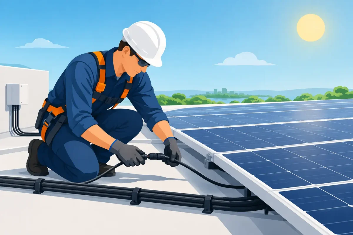
On rooftops, cables should not be left loose on surfaces that accumulate water, dirt, or excessive heat. The fastening must keep the circuit organized, away from sharp edges, and protected against movement caused by wind, vibration, or thermal expansion. Clamps and accessories must also be compatible with UV radiation and the operating environment. A low-durability accessory may break before the cable, leaving the circuit vulnerable.
At the entrances of boxes, inverters, and panels, use cable glands and sealing elements suitable for the cable's outer diameter. Sealing cannot rely on makeshift solutions using insulating tape or sealant. In addition to reducing the overall protection, improvised solutions encourage the entry of moisture and contaminants.
Infrastructure sharing between DC, AC, control, and communication circuits must be carefully evaluated. Segregation facilitates identification, reduces interference, and improves safety during maintenance activities. In some projects, physical separation is mandatory by standard or by equipment manufacturer requirements.
Connectors and terminations require proven compatibility.
A significant portion of localized heating incidents in photovoltaic systems is associated with improper connections. A connector that looks similar to another is not necessarily compatible. Mixing components from different manufacturers, with different geometries or crimping systems, can result in poor electrical contact, loss of tightness, and risk of arcing.
The assembly must use a crimping tool compatible with the terminal, conductor cross-section, and manufacturer's recommendations. After crimping, visual inspection does not replace the mechanical and dimensional verification defined in the procedure. Poorly inserted conductors, deformed terminals, and incomplete locks are defects that may remain hidden until the installation is live.
In switchboard and inverter terminations, the torque must follow the equipment specification. Insufficient torque increases contact resistance; excessive torque can damage terminals, threads, or the conductor itself. Recording these values in a commissioning report improves traceability and reduces diagnostic time in future maintenance.
Grounding, equipotential bonding, and protection are not complementary elements.
Metal structures, equipment casings, cable trays, and other masses must be integrated into the grounding and equipotential bonding strategy defined in the project. The objective is not only to meet a documentary requirement, but to create controlled paths for fault currents and reduce dangerous potential differences.
Surge protection and lightning protection need to be coordinated with the physical layout of the installation. Extensive cable routes, unnecessary loops, and poorly positioned grounding conductors increase the system's susceptibility to induced overvoltages. There is no single solution for every plant: the exposure level, topology, existing grounding system, and risk analysis define the appropriate design.
Commissioning: validate before putting the generation into operation.
The installation must be released after inspections and tests compatible with the system scope and applicable procedures. ABNT NBR 16274 is a relevant reference for verification and documentation of grid-connected photovoltaic systems. Furthermore, the activities must comply with the safety requirements of NR-10 and the internal operating procedures.
A well-executed commissioning routine typically verifies circuit identification, polarity, continuity of protective conductors, insulation resistance, connection tightness, and visual integrity of routing. In more critical systems, electrical string measurements, load thermography, and photographic records provide important evidence for acceptance and maintenance.
The final documentation must reflect what was installed in the field. Updated diagrams, cable lists, calculation reports, certificates, technical data sheets, test reports, and string identification prevent a simple intervention from turning into a prolonged shutdown. For EPC contractors, integrators, and asset managers, this set of documents also supports warranty and expansion decisions.
Innovcable develops solutions for projects where electrical performance, environmental resistance, and traceability need to go hand in hand. When the application requires a specific construction, engineering analysis should occur before purchase, not after failure.
A well-installed photovoltaic system doesn't depend on frequent repairs to continue generating energy. It is born from precise specifications, disciplined assembly, and thorough inspection – three decisions that preserve the energy produced and confidence in the asset.